Spur Gears r.02.1
Description
Spur gears are the most common type of gears used in industry and they have straight, flat-topped teeth set parallel to the shaft.
This web application creates an external spur gear by the simulation of the movement of the rack cutter and provides the following main tasks:
- calculate the geometric parameters of the gear,
- draw an accurate image of the gear with a detail of the teeth,
- adjust the tooth thickness by use of correction (optimization of toothing),
- calculate the tooth root bending stress with the Lewis method,
- return a DXF file containing the 2D profile of the gear to be used with 2D and 3D CAD software.
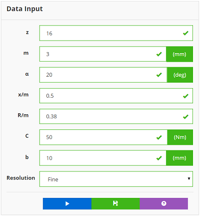
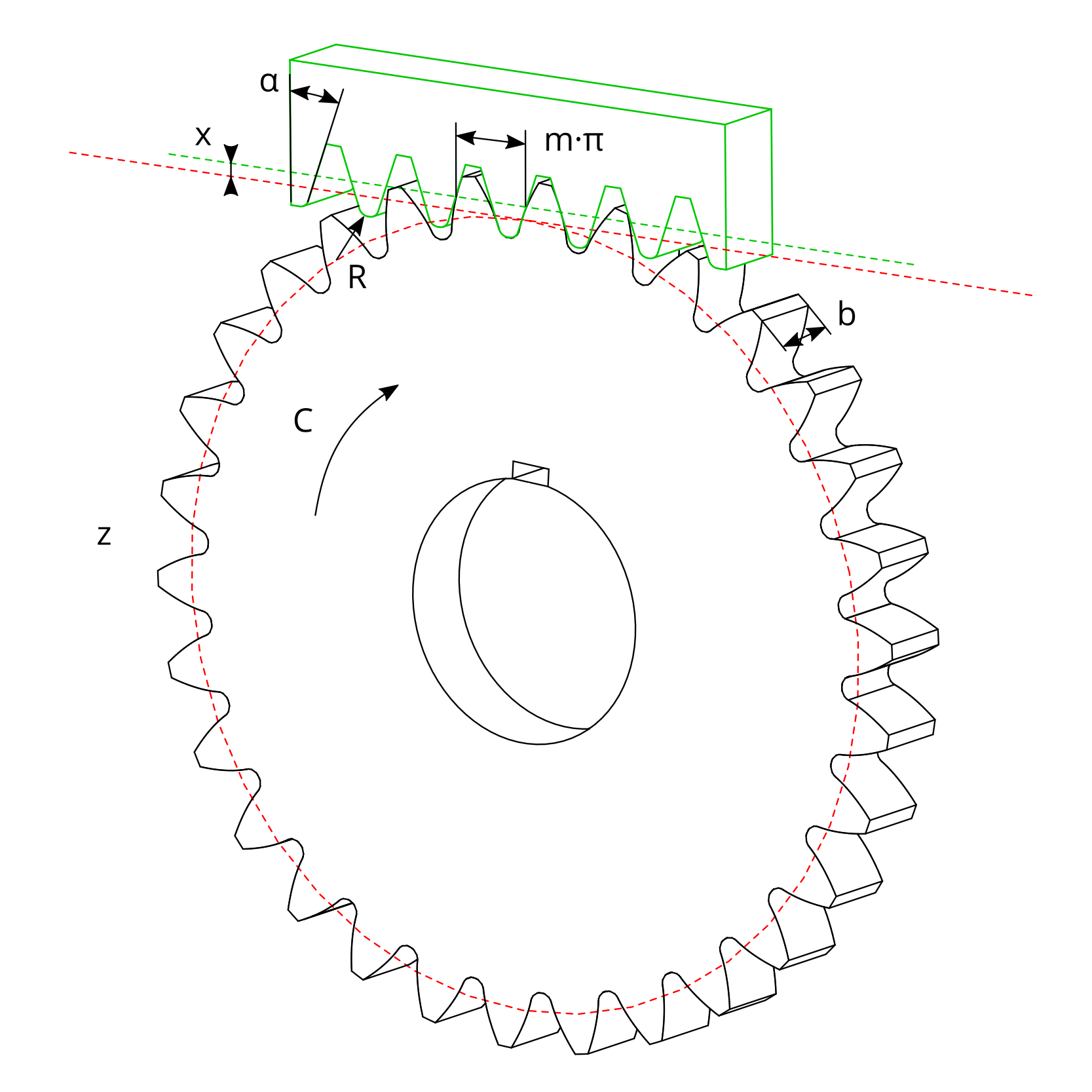
To create the gear insert the following parameters in the input form:
- the number of teeth z,
- the module m,
- the pressure angle α,
- the rack shift coefficient x/m for the adjustment of the tooth thickness,
- the coefficient of fillet radius of the rack cutter R/m,
- the static nominal torque C applied,
- the face width b of the tooth.
Standard gears
For standard gears, the pressure angle α is 20°, the coefficient of fillet radius of the rack cutter R/m is equal to 0.38 (type A basic rack tooth profile - ISO 53:1998) and the rack shift coefficient x/m is 0.
Set afterwards the Resolution - Coarse, Medium or Fine - and click on the "Run" button  .
.
If there is no undercut, the software calculates the tooth root bending stress using the Lewis method, provides the geometric parameters of the gear
and generates the DXF profile of the gear where the tooth profile is the true involute curve and the base radius is the true trochoid curve.
Tooth root bending stress
The tooth root bending stress σF occurs with the application of the load at the outer point of a single tooth:
σF = Fbt / (b·m·YL)
where YL is the form factor which takes into account the influence of the tooth form.
The tooth root bending stress σF doesn't take into account variation due to applied torque, dynamic effects, inaccuracies in manufacture,
elastic deformations, geometric tolerances, local stress effects due to the change of section at the tooth root, rimmed gears, etc.
To download the DXF profile of the gear, click on the "Download DXF Profile" button  and use it with your favourite CAD software.
For the meaning of the terms used in the software and for additional information regarding spur gears,
click on the "Spur Gears Help" button  .
.
Warning! There is an undercut!
Well done! You successfully create your spur gear!
Data Input
Spur Gear Image
Example #1 - Standard spur gear
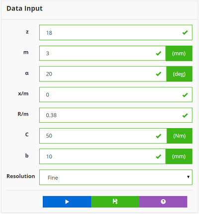
Consider to create a m=3 standard gear
- α=20°
- x/m=0
- R/m=0.38
with the number of teeth equal to 18 - the minimum number to not have geometric undercut effects.
The gear has a face-width of 10 mm and a 50 Nm static torque is applied.
Here below are the input data and the corresponding image of the gear created clicking the "Run" button  .
.
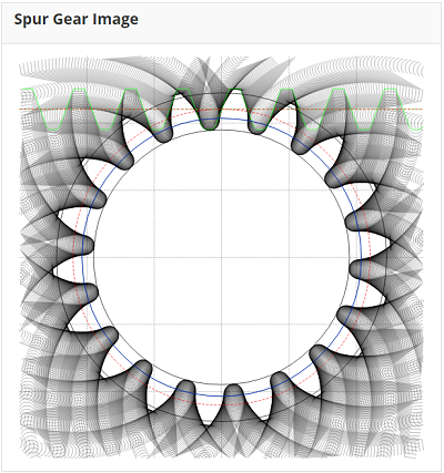
The table of results provides:
- the minimum and the maximum rack shift coefficient (x/mmin and x/mmax);
- the reference diameter (d);
- the base diameter (db);
- the involute tooth limit diameter (dlim);
- the root diameter (df);
- the addendum diameter (dt);
- the tooth root bending stress at point T (σF);
- ...
Example #2 - Spur gear corrected tooth
Consider to create the same gear of the Example #1 but with the number of teeth equal to 16.
To do this it's necessary to correct the tooth of the gear using a shift coefficient x/m = +0.5.
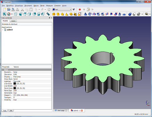
Here below are the input data and the corresponding gear created with a 3D cad software using the downloaded DXF profile.
