Spur Gears Help
Spur Gears is a web application that creates involute spur gears and provides the following main tasks:
- calculate the geometric parameters of the gear,
- draw an accurate image of the gear with a detail of the teeth,
- adjust the tooth thickness by use of correction (optimization of toothing),
- calculate the tooth root bending stress with the Lewis method,
- return a DXF file containing the 2D profile of the gear to be used with 2D and 3D CAD software.
This help page gives a complete clarification of the meaning of the terms used in the software and additional information regarding spur gears as formulas, an useful bibliography, a numerical example and tips about gear tooth correction.
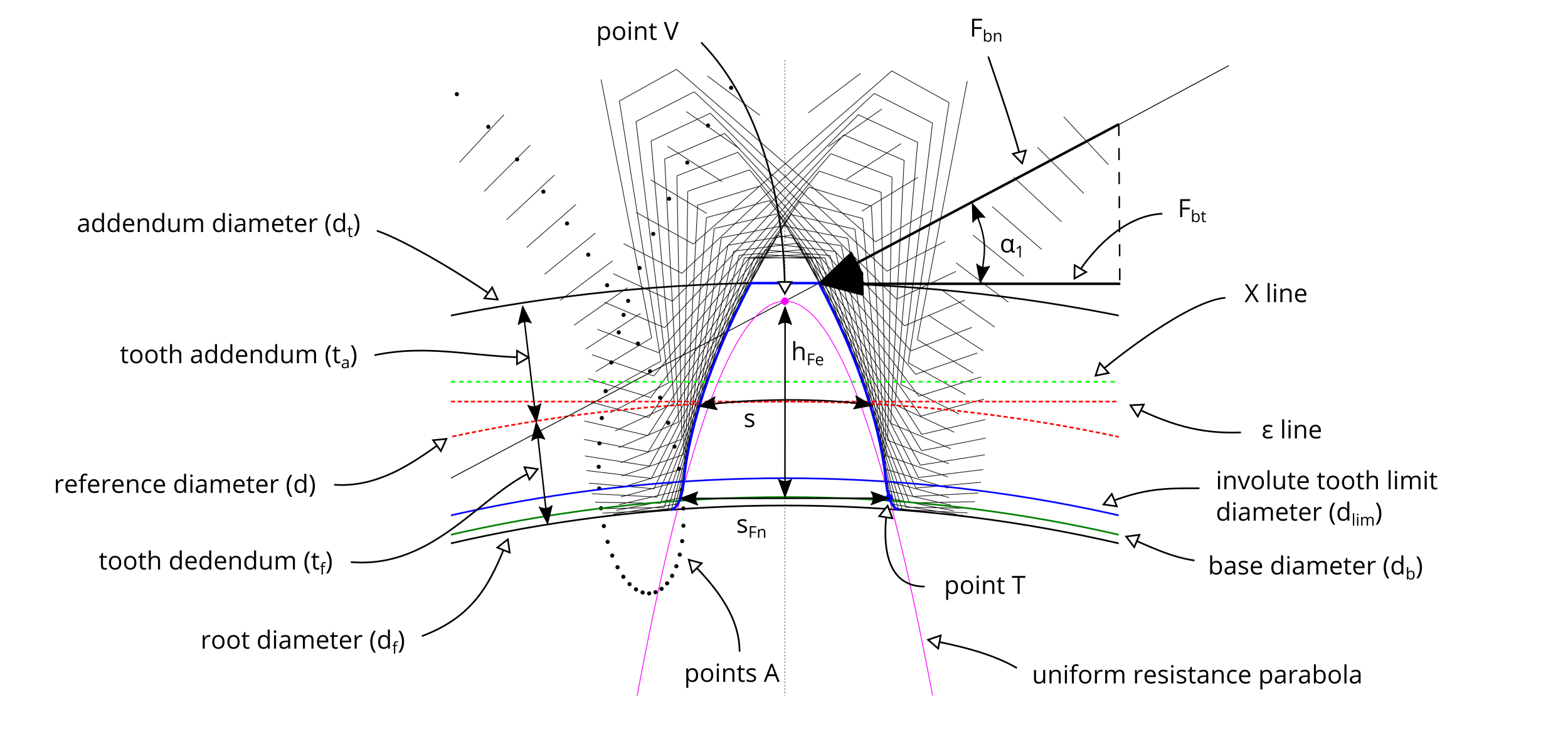
Figure #1 contains a visual representation of the terms related to spur gears and to the tooth root stress calculation.
#1 - Detail of a spur gear

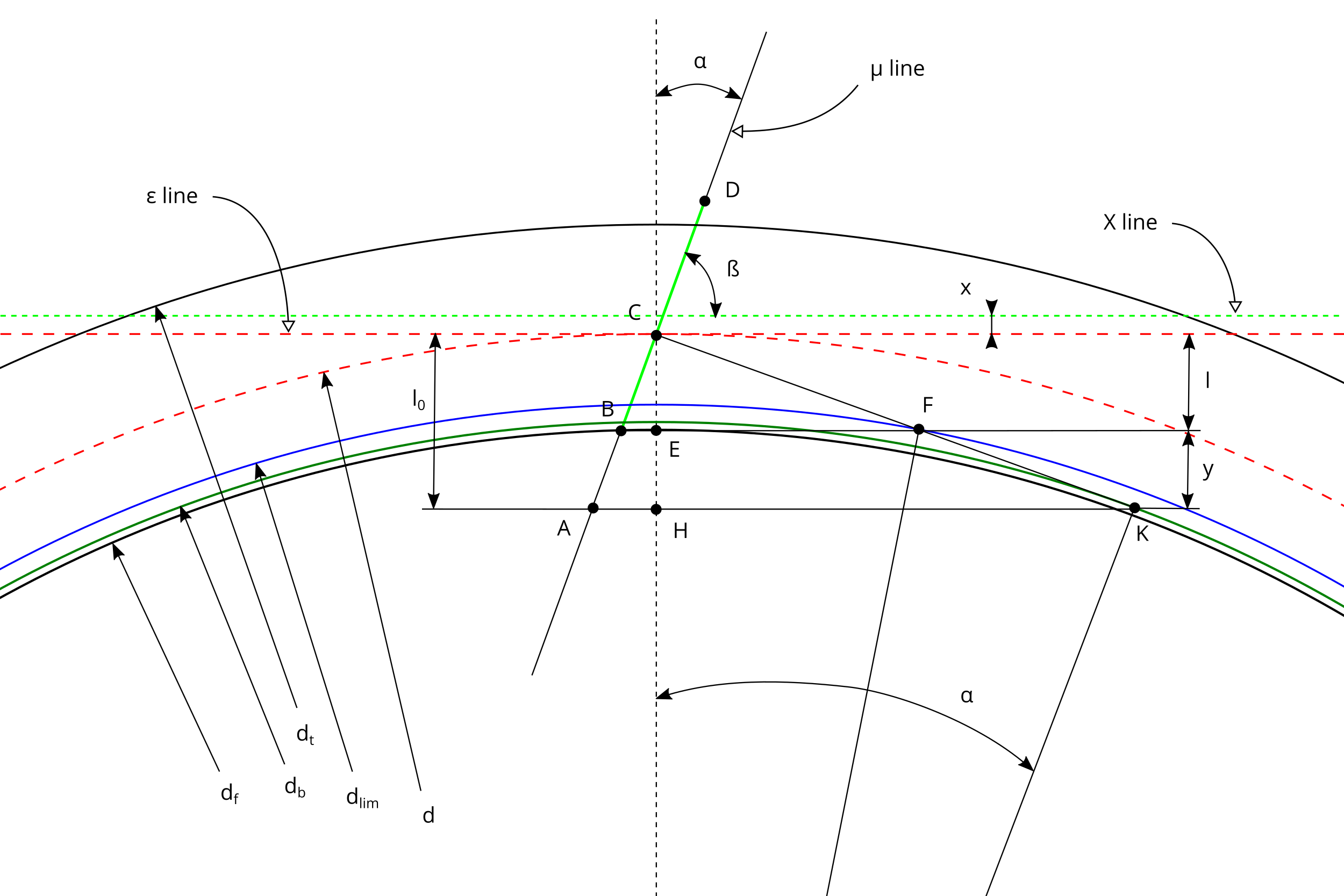
In figure #2 there is the schema used to generate the involute profile of the tooth of the gear.
#2 - Involute schema to create the gear

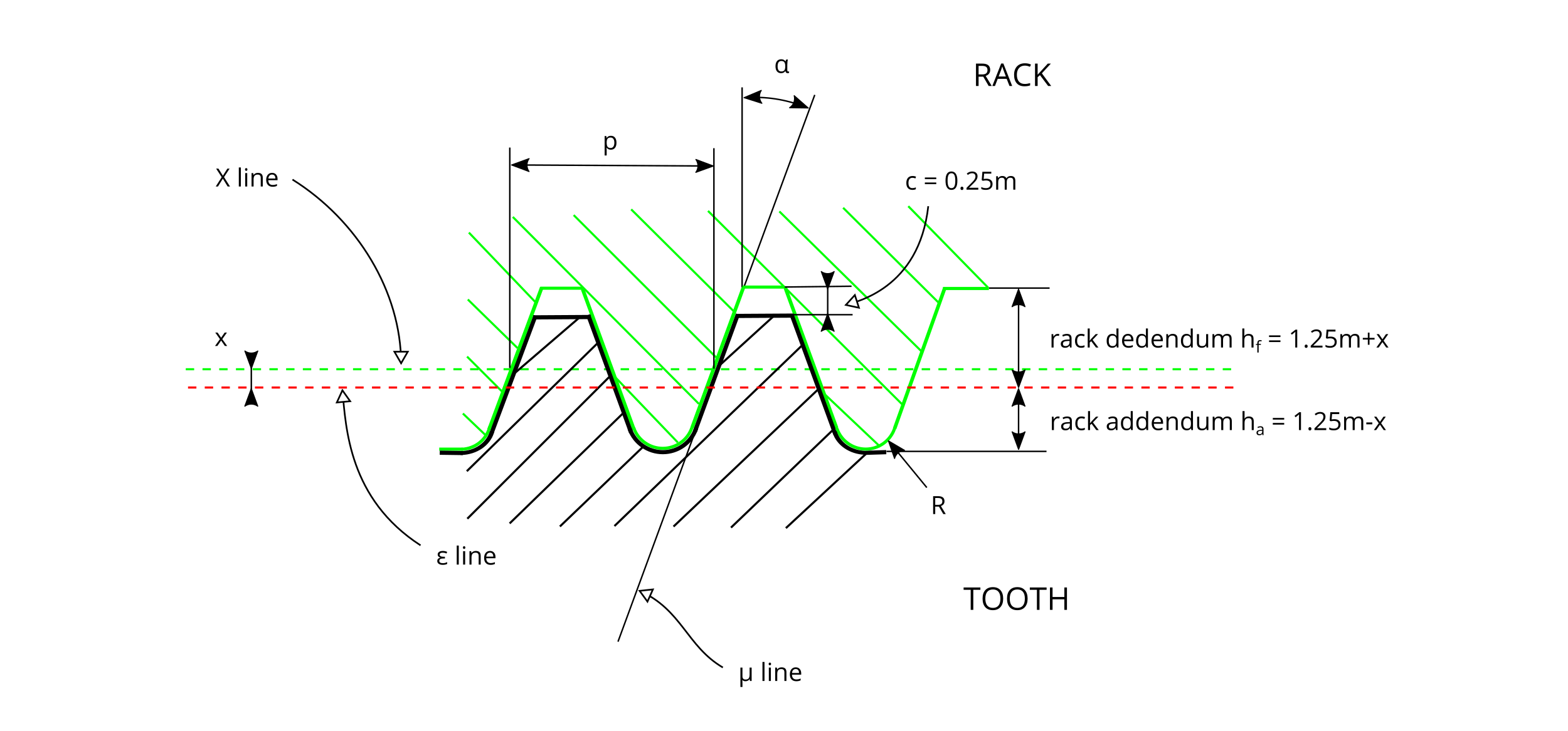
Figure #3 represents the rack cutter used to generate the gear, as defined in ISO 53:1998.
#3 - Rack tooth profile

In the following table there are a numerical example and some basic formulas related to standard spur gears valid if R/m = 0 and x/m = 0.
| Element | Formula | Example |
| number of teeth | $$z$$ | 30 |
| module | $$m$$ | 5 mm |
| pressure angle | $$ \alpha $$ | 20° |
| rack shift coefficient | $$ x/m $$ | 0 |
| coefficient of fillet radius of the rack cutter | $$ R/m $$ | 0 |
| static nominal torque | $$ C $$ | 250 Nm |
| face width | $$ b $$ | 10 mm |
| $$ l_0 = \frac{d} {2} \cdot {sin}^2(\alpha)$$ | 8.77 mm | |
| $$ \frac{y} {d/2} = \frac{2.5} {z} - {sin}^2(\alpha)$$ | -0.0336 | |
| $$ l = l_0 + y$$ | 6.25 mm | |
| pitch | $$p = {m \cdot \pi}$$ | 15.71 mm |
| reference diameter | $$d = {m \cdot z}$$ | 150 mm |
| base diameter | $$d_b = d \cdot cos(\alpha)$$ | 140.95 mm |
| involute tooth limit diameter | $$d_{lim} = 2 \cdot \sqrt{ \left( r-l \right)^2+\left( \frac{l}{tan(\alpha)}\right)^2}$$ | 141.72 mm |
| root diameter | $$d_f = d - 2 \cdot l$$ | 137.5 mm |
| addendum diameter | $$d_t = d + 2 \cdot m $$ | 160 mm |
| tooth addendum | $$t_a = m $$ | 5 mm |
| tooth dedendum | $$t_f = 1.25 \cdot m $$ | 6.25 mm |
| circular reference tooth thickness | $$s = \frac{m \cdot \pi}{2} $$ | 7.85 mm |
| $$z_{min} = 1.25 \cdot \frac {2} {{sin}^2(\alpha)} $$ | 22 | |
| rack addendum | $$h_a = 1.25 \cdot m $$ | 6.25 mm |
| rack dedendum | $$h_f = 1.25 \cdot m $$ | 6.25 mm |
| nominal load, normal to the line of contact | $$F_{bn} = \frac {C} {d/2 \cdot cos(\alpha)} $$ | 3547.26 N |
| $$ \alpha_1 $$ | 26.92° | |
| nominal transverse load in plane of action | $$F_{bt} = F_{bn} \cdot cos(\alpha_1) $$ | 3162.85 N |
| tooth root chord at the critical section | $$ s_{Fn} $$ | 9.74 mm |
| bending moment arm relevant to load application at the tooth tip | $$h_{Fe} $$ | 9.4 mm |
| tooth form factor - Lewis method | $$Y_{L} = \frac {{s_{Fn}}^2} {6 \cdot h_{Fe} \cdot m} $$ | 0.3361 |
| tooth root bending stress at point T | $$\sigma_{f} = \frac {F_{bt}} {Y_L \cdot b \cdot m} $$ | 188.21 N/mm2 |
Gear ratio
The gear ratio $\tau$ of a gear train is the ratio of the angular velocity of the input gear to the angular velocity of the output gear:
$$\tau=\frac {\omega_1} {\omega_2}=\frac {d_2} {d_1}=\frac {z_2} {z_1}$$
where
$\omega_1$ is the angular velocity of the input gear e $\omega_2$ is the angular velocity of the output gear;
$d_1$ is the reference diameter of the input gear e $d_2$ is the reference diameter of the output gear;
$z_1$ is the number of teeth of the input gear e $z_2$ is the number of teeth of the output gear.
Center distance
For a pinion and a wheel without correction (x/m = 0) or in case of complementary correction (e.g. the pinion with a positive correction x/m = +0.5 and the wheel with a negative correction x/m = -0.5), the center distance $i$ is calculated with the formula: $$i = \frac {d_1} {2} + \frac {d_2} {2} = \frac {m \cdot (z_1 + z_2)} {2} $$ In case $x_1+x_2\neq0$, the center distance $i'$ is different from $i$ and may be calculated solving the following formulas: $$ inv(\alpha')= \frac {2 \cdot (x_1+x_2) \cdot tan(\alpha)} {m \cdot (z_1 + z_2)} + inv(\alpha)$$ $$i'=i\cdot\frac {cos(\alpha)} {cos(\alpha')}$$ where $ \alpha' $ is the working pressure angle, different from the pressure angle $ \alpha $ of the rack cutter.
Clearance
The pinion-wheel clearance $c$ depends from the value of $(x_1+x_2)$ and may be calculated with the formula $$c=m\cdot\left[0.25-\frac {x_1+x_2} {m}+\frac {z_1+z_2} {2}\cdot \left( \frac {cos(\alpha)} {cos(\alpha')}-1\right)\right]$$ For gears with $x_1+x_2=0$, the clearance is equal to 0.25m (type A basic rack tooth profile - ISO 53:1998).
Resolution
In the software, it is possible to set the resolution of the involute generating process of the gear.
Here are the meaning and the associated values of the Resolution parameter:
| Pitch of the movement of the rack cutter to create the gear image | Number of points of the involute profile of the flank of the tooth | |
| Coarse | 4 deg | 5 |
| Medium | 2 deg | 10 |
| Fine | 1 deg | 20 |
Bibliography
[1] - Georges Henriot - Ingranaggi - Trattato teorico e pratico - Vol. I e II - Tecniche Nuove - Ed. 1977
[2] - Lodovico Soria - Tecnica degli ingranaggi : trattato teorico-pratico di calcolo, correzione, dentatura, misura, trattamento termico, finitura e controllo ingranaggi cilindrici, elicoidali,
a catena, conici dritti e conici spiroidali - Editore Viglongo - Torino - Ed. 1971
[3] - prof. Paolo Righettini - Progettazione funzionale di sistemi meccanici - Ruote Dentate - Università degli Studi di Bergamo - Italy
[4] - ISO 6336-1:1996 - Calculation of load capacity of spur and helical gears - Part 1: Basic principles, introduction and general influence factors
[5] - ISO 6336-3:2006 - Calculation of load capacity of spur and helical gears - Part 3: Calculation of tooth bending strength
[6] - ISO 53:1998 - Cylindrical gears for general and heavy engineering - Standard basic rack tooth profile
[7] - Gear - en.wikipedia.org/wiki/Gear
